Description
PD Free AC Resonant Test Set , Partial Discharge Test Equipment No More Than 10pC
Detailed Product Description

PD Free Resonant Withstand Voltage Test Set , Transformer Induced Voltage Withstand And Partial Discharge Test
I. Products description :
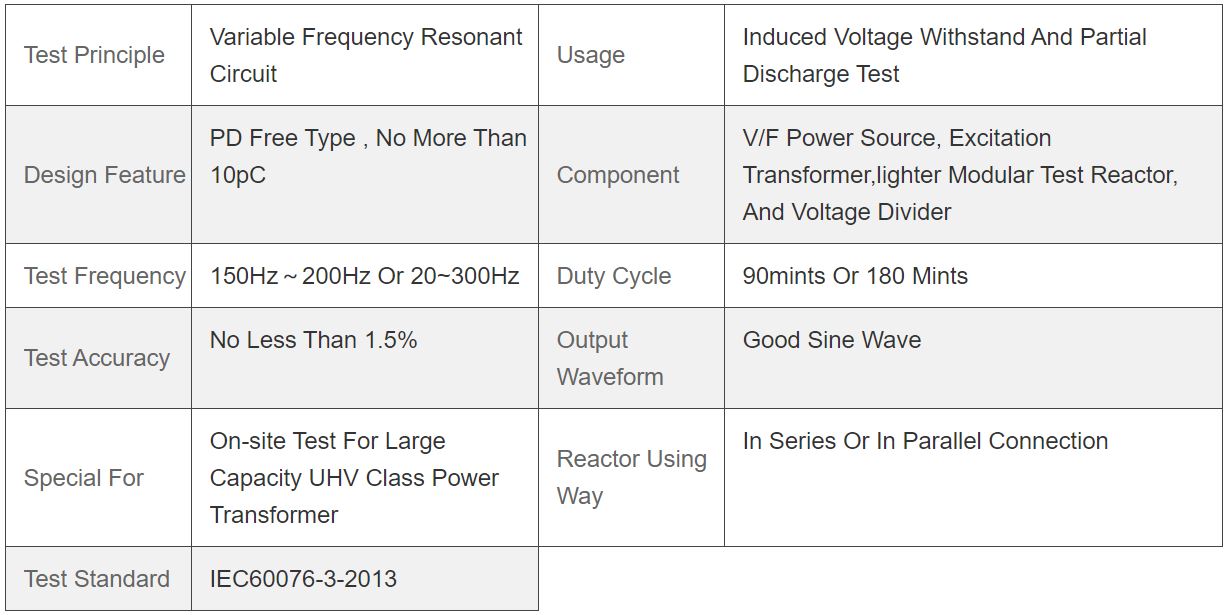
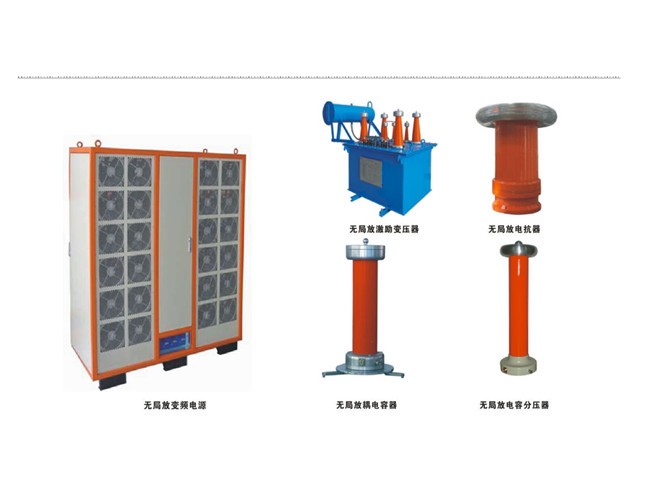
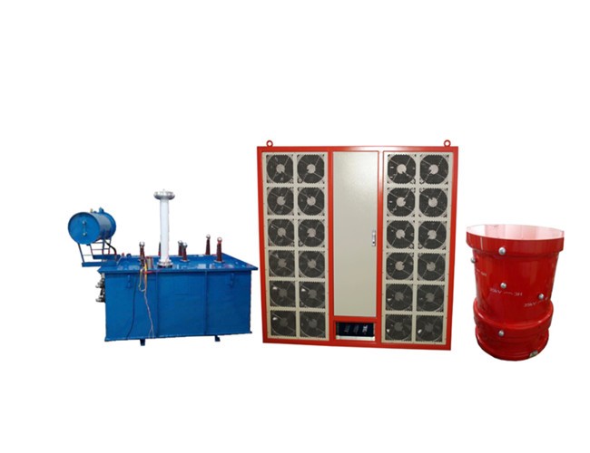
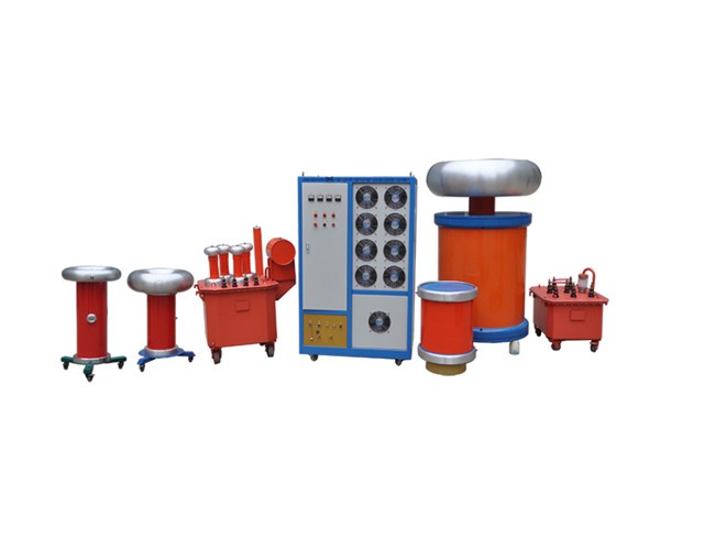
HTXB-WJF series test system is mainly used for field induced voltage withstand and partial discharging test of power transformers 110KV class and above. This system adopts PD free push-pull variable-frequency power source technique which ensure fine sine wave and proper test frequency output during testing under iron core unsaturated condition of power transformer .The system can also be designed compatible to test long distance XLPE cable or HV GIS.The above pictures is for transformer induced voltage withstand &partial discharge test system made by HONGTE to testing for 220KV power transformer in the field.
Induced voltage withstand test(IVWT), also called induced overvoltage withstand test ,ACSD,ACLD, DVDF, is one of most important dielectric test of power transformers.As per IEC60076-3-2013, IVWT is necessary routine test and acceptance test ater installation for abobe 110KV Power transformer .
II. Applicable objects
- Transformer with Graded insulation of 110KV
- Transformers of 220KV,500KV,750KV,1000KV Class.
- AC voltage withstand test can be made for GIS, transformers,switches,bushing and cables nomore than 1000kv if equipped with proper series resonance HV reactors.
III. System Composition
- PD free push-pull variable-frequency power source&observe&controlling cabinet,
- PD free excitation transformers,
- Loss compensation test reactor,
- Partial discharging test instrument
- Coupling Voltage divider
- Necessary test accessories
- Linear power amplifier circuit designed, whole sine wave output, little wave distortion.
- Multiple protection includes:discharge breakdown protection, over voltage setting protection,output short-circuit protection,start up null position protection,bridge arm amplification loop protection, power curve protection. Any kind of the above protection works, voltage output will be blocked immediately the major loop power supply will be cut off to guarantee the safety of personnel,tested objects and test system.
- The signal source of the device is produced from dedicated chip,the output frequency stability can be as high as 0.0001Hz. and the output voltage is controlled by singlechip which guarantee the degree of instability of voltage less than 1%.
- With setting function of test parameters such as test voltage and time, automatic and manual controlling methods.
- With voltage automatic stabilization adjustment function, constant output of voltage when frequency regulation within the scope of settled.
- Optical controlled,insulated completely HV and low voltage control loops.
- Continuously adjustable in a test frequency range of 20—400Hz and with automatic look-up function of resonance frequency. Being able to set multistage of frequency detection.
- LCD display and multiple rotary mouses controlled, friendly human-computer interface, simple and convenient for operation and wire drawing.
- The variable frequency power source is shielded by high permeability magnetic material with ability of anti-strong disturbance of electric field and ensure the measurement accuracy and stability.
- This device can be equipped with special test vehicle and container together
V. General Technical Data:


